Z-Wave Regulatory Process
Introduction
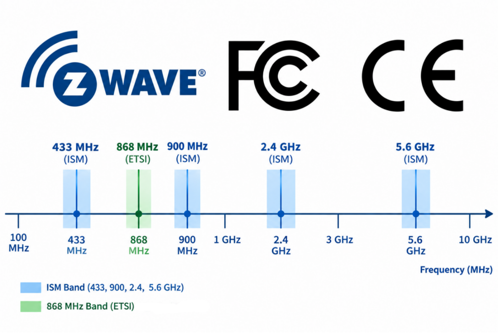
Z-Wave IoT devices are Intentional Radiators of radio waves in the license free International Telecommunication Union (ITU) Industrial, Scientific, and Medical (ISM) spectrum in most of the world except for Europe. Europe uses the 868MHz band in a similar fashion but is regulated by the ETSI and CEPT although it is often incorrectly referred to as being part of the ISM band. Since the rules are nearly the same, we can reasonably call it all the “ISM band”.
The key requirement for all Intentional Radiators is that they must not cause harmful interference and must accept any incoming interference. The exact rules that must be followed are complex and detailed in the respective standards. I provide a summary of the important parts in this post but, your results may vary and I defer to your expert testing agency.
Z-Wave Long Range (ZWLR) has the advantage of being spread-spectrum and the rules allow up to +30dBm of radiated power in the US. Since the Z-Wave chips have a maximum power of only +20dBm, there is typically plenty of margin. The test house will still need to check but ZWLR is normally not an issue for regulatory testing. The main concern is Z-Wave mesh which uses FSK modulation at 0dBm in the US and +14dBm in the EU. The narrow band FSK signal can exceed the regulatory requirement in certain orientations or in certain modes of operation. Working with a regulatory expert will save money in the long run and keep the product release date on schedule.
Best Practices
Typically, a test house will perform the necessary RF tests using specialized equipment. The goal is for the testing to be completed in less than one day. The costs are significant, starting at $10,000 or more, and any delays will incur additional charges. Each test house and each test technician will perform the tests differently. Some are much stricter and some are more forgiving. Be prepared to respond to issues with updated firmware while on-site. Testing can blow the schedule so be sure to plan the RF testing early enough to respin the PCB if needed, especially if using a PCB antenna.
- Send several units of each type
- Just in case a unit dies or is failing RF testing
- Clearly label the function of each unit
- Include detailed setup instructions with photos
- How to wire power supplies or batteries
- How to connect the UART
- Include detailed step-by-step instructions
- How to adjust the TX Power level for Z-Wave Mesh
- If allowed, send an engineer along with tools to rebuild and change firmware
- Pre-Test as much as possible & work with a regulatory expert
FCC in the USA
General low-power Intentional Radiators section 15.249 is the primary requirements document. Section 15.5 describes the general requirement that devices must operate on a non-interference basis and must accept received interference. Sections 15.209 and 15.205 specify the limits for emissions below the fundamental. Section 15.207 must not conduct radio waves onto the AC power lines. Section 15.201 specifies the requirement to undergo formal FCC equipment authorization.
Section 15.249 specifies any emissions outside of 902-928 must be attenuated by at least 50dB of the fundamental (there is more complexity to this rule, but this is worst case). This is often the challenge with Z-Wave Mesh where the 2nd, 3rd, 4th or 5th harmonic may have spurious emissions above this requirement. These emissions can be caused by a poor ground plane, PCB layout of the matching passive components, the antenna itself or any of a host of other issues.
The main configuration setting for regulatory purposes is to measure the values for APP_MAX_TX_POWER_LR, APP_MAX_TX_POWER and APP_MEASURED_0DBM_TX_POWER (in deci-dBm) which are entered into the file config_rf.c. These are the three parameters that set the maximum radio transmit power. APP_MAX_TX_POWER_LR is simply set to the maximum power the chip can support, either +14dBm (+140 in deci-dBm) or +20dBm. The APP_MEASURED_0DBM_TX_POWER is normally set to zero unless the antenna has significant gain. The APP_MAX_TX_POWER is then set based on measurements at all frequencies, orientations and looking at spurious emissions and other rules. Ideally, it is also set to zero but often must be set slightly lower to meet the regulatory rules. If it is set below -4.0dBm, you should understand the issue in detail and consider redesigning the antenna, the PCB and filtering circuits. Lower settings may result in not meeting the minimum RF range for Z-Wave Mesh and poor RF range performance.
What I dislike about this flow is that the transmit power is measured at the test house using totally different firmware (RAILTest or Radio CLI) instead of the application firmware. Ideally there would be a mode in the application firmware to put the radio into a carrier wave mode to ensure the application and the SDK are properly setting the maximum transmit power. This has been requested for years but so far hasn’t reached the priority list. The main reason to NOT enable this feature is that it is far too easy for a firmware bug to turn the transmitter on, resulting in a Z-Wave jammer. In the early days of Z-Wave there were a few devices that would become a jammer. This resulted in the removal of this feature from the application SDK. Finding jammers is a difficult task for experienced RF engineers and virtually impossible for the average Smart Home consumer.
Spurious Emissions
There are many parts to the regulatory testing but the most common problem I have seen is spurious emissions at an
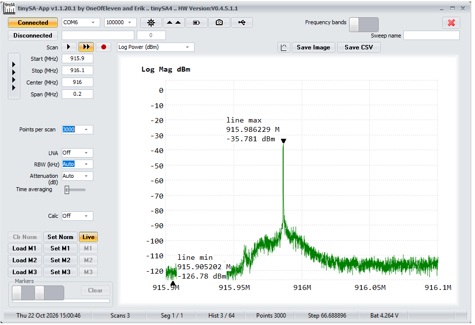
integer multiple (2,3,4,5) of the fundamental. The FCC rules require spurious emissions to be 50dB below the fundamental (there’s way more to this rule than I can describe here but this is a worst case). In the example shown here, the fundamental is 916MHz with a -36dBm measured power. Note that I’m using an inexpensive spectrum analyzer which is not calibrated for the level of accuracy required but is OK for a quick check. The test house will use very expensive and calibrated equipment.
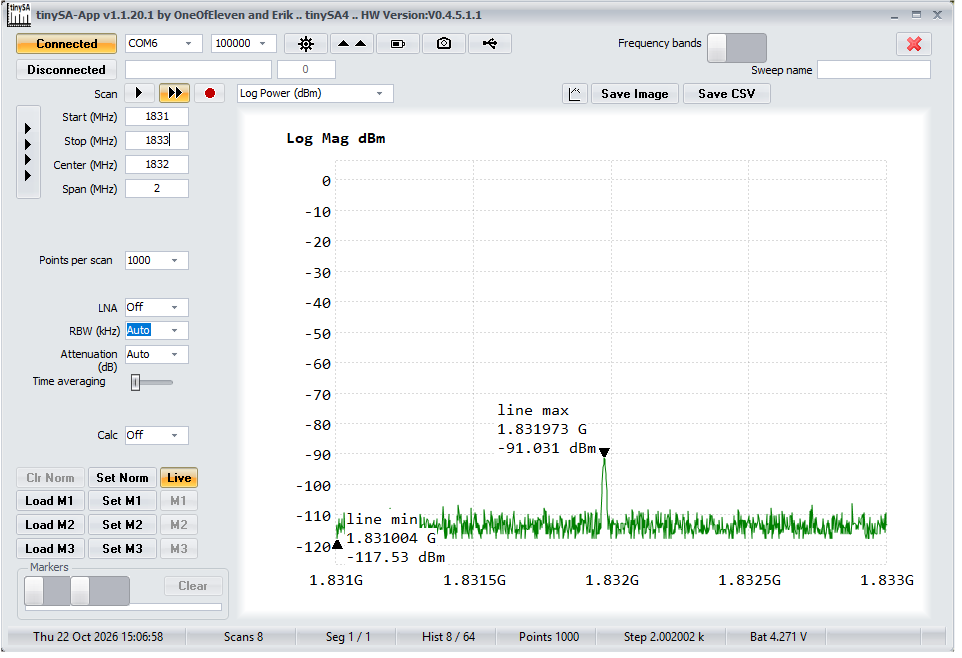
The second harmonic is at 1.8GHz with a power of -91DbM which is 55dBm below the fundamental, so it meets the FCC requirement with 5dBm to spare, but that’s not a lot of margin.
Spurious emissions are sometimes problematic at integer multiples of the crystal frequency. The challenge here is the broadcast FM band (89-108MHz) has tight restrictions. Silicon Labs uses a 39MHz crystal which has the FM band between the second and third harmonic. Trident uses a 32MHz crystal which has the third harmonic at 96.0 MHz on the FM dial making the PCB layout of the crystal critical.
Silicon Labs RAILTest
RAILTest is the Silicon Labs Radio Abstraction Interface Layer (RAIL) test tool that runs on the Z-Wave chip. The tool uses the command line to enter commands for the radio to output the desired test signal. RAILTest is a complex tool with hundreds of commands of which only the few listed below are the ones needed for Z-Wave testing. Fortunately, all commands needed to test Z-Wave are built-in, so no customization of the radio configuration is required. RAILTest must be built using Simplicity Studio for the specific Z-Wave chip. Then flashed to the board and a UART terminal connection made to the device. See this KBA for the procedure to map the measured maximum TX power level into the values to be compiled into the code.
RAILTest in the 2026.6.2 SDK release needs two additional software components: CLI:Storage in NVM3 which depends on NVM3 Default Config. These are needed to store scripts in flash which are needed to have the device automatically power up and run the script to output a carrier wave. In the Software Components of the project, search for NVM3 and “install” the CLI:Storage in NVM3 component which must be named “inst0”. Then build and flash the project onto your device.
RAILTest Z-Wave Command List
| Command | Description |
| set rx 0 | Put the radio into IDLE mode to enable other settings |
| setzwavemode 1 3 | enable Z-Wave mode |
| setchannel [0-3] | Frequency depends on the region
0=100kpbs FSK (912MHz)Z-Wave Mesh modes 1=40kbps FSK (908MHz) 2=9.6kbps FSK (908.42MHz) 3=100kbps DSSS-OQPSK (916MHz or 912) ZWLR |
| setpower [-127-+127] [raw] | Transmit power in decidBm (0.1dBm)
RAW uses “raw” register value [0-200] The command echoes both the RAW and decidBm value |
| settxstream [0-1] | Modulated Carrier wave transmit on/off
PN9 random stream |
| settxtone [0-1] | Unmodulated Carrier wave transmit on/off |
| enterscript [1-5] | Start script capture – up to 5 scripts
End with “endscript” |
| clearscript [1-5] | erases the chosen script |
| printscript [1-5] | list the script |
| runscript [1-5] | Run the script |
Sample Script
This script will run at power on and output a 916MHz unmodulated carrier. Typically the test house wants devices that will simply power up and output an unmodulated carrier at the required frequencies. You can send fewer devices with instructions on how to change the frequency and modulation but of course that increases the time for testing.
| clearscript 1 | Remove any previous script |
| enterscript 1 | starts capturing script #1 |
| rx 0
setzwavemode 1 3 setzwaveregion 11 setpower 200 setchannel 0 settxtone 1 endscript |
Paste this in to create the script |
| printscript 1 | check that it was entered properly |
| reset | reset the chip – the script should autorun and be transmitting |
Trident Radio CLI
Trident IoT has a similar command line application that is built and flashed using their elcap tool. The Radio CLI is a sample application with the necessary features for regulatory testing. Tridents tool is simpler with good documentation and command completion (press TAB) which helps those of us with fat fingers. The tool is easily built, downloaded into your board and the UART connected through a Segger J-Link. Note that in the 2026.06 SDK the default baud rate for the UART is 230400, double the usual 115200 using the command “elcap device tty –baudrate 230400 –usb <J-Link SN>”.
Radio CLI Z-Wave Command List
The complete command list can be found here. The list below are the commands needed for regulatory testing.
| Command | Description |
| zw_init | Initialize the radio |
| zw-region-set [0-103] | 0=EU, 1=US Mesh, 2=ANZ, 3=HK, 9=USLR, |
| zw-tx-channel-set [0-3] | Frequency depends on the region
In region 9 USLR 0=916, 1,2=908.42,3=912 |
| zw-tx-power-set [-20-+20] | Transmit power in dBm |
| zw-radio-tx-continues_set [on,off] [0-2] | Carrier wave transmit on/off
0=unmodulated, 1=modulated fixed pattern, 2=modulated whitened |
| rx [on,off] | Turn receive on/off |
| script start [1-5] | Start script capture – up to 5 scripts
End with “.done” |
| script [autoon,autooff] [1-5] | Enable/disable automatically running the script on power on |
| script load [1-5] | Bulk enter a multi-line script |
| run [1-5] | Run the script number |
| wait # | Wait # milliseconds |
| status | Display the current status of the radio |
Sample Script
This script will start on power on and output a 916MHz unmodulated carrier.
| script load 1 | enables loading the script on the next row |
| zw-init
zw-region-set 9 zw-tx-channel-set 0 zw-radio-tx-continues_set on 0 .done |
Paste this in to create the script |
| script autoon 1 | Enable automatically running the script on power on |
| reset | reset the chip – the script should autorun and be transmitting |
Next Steps
The final part 10 of the Z-Wave Developer’s Journey discusses volume manufacturing and how to program, test and print the QR codes required for all certified Z-Wave devices. As we continue along the Z-Wave Developer’s Journey, I welcome your comments and questions. Please feel free to reach out to me directly via email.
About the Author
Eric Ryherd has been at the forefront of Z-Wave innovation since 2003, beginning as a consultant and later serving as a Field Application Engineer at Silicon Labs. Over the course of his career, he has contributed to the design and development of a wide range of Z-Wave products, including sensors, remote controls, motorized window shades, and in-wall dimmers, many of which are on the market today.
Although he “retired” in 2022, Eric remains deeply engaged in embedded systems and Z-Wave development through his blog, DrZWave.blog, and ongoing IoT consulting projects. He is also a familiar face at Z-Wave Alliance Unplug Fests, where he frequently serves as the lead coordinator, supporting interoperability and developer collaboration.