
Optimizing Z-Wave IoT Devices to Achieve 10+ Year Battery Life
Learn how to optimize Z-Wave IoT devices for 10+ year battery life with practical guidance on sleep modes, power consumption, troubleshooting, and measurement tools for Z-Wave developers.
Introduction
Wireless IoT devices are typically powered with batteries. Thus, a key design criterion is: how long will the batteries last? Z-Wave developers must balance battery lifetime, battery type and functionality. Simple Z-Wave sensors can run on a single coin cell for five to as many as ten years. Door locks need four AA batteries to mechanically throw the locking bolt, but the electronics still contribute significantly to battery life. Most devices need at least a two-year battery life otherwise customers feel they are constantly changing batteries resulting in a one-star review.
There are three components of battery life calculation:
- Average current while sleeping
- Average current while awake
- Awake duration
Battery lifetime calculation:
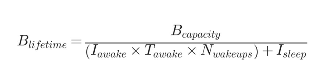
For example: A device with 3 AAA batteries has a capacity of 1000mAhr, an average awake current (Iawake) of 12mA for 0.2 seconds (Tawake) with 6 wakeups per hour (Nwakeups) and an average sleep current (Isleep) of 0.030mA, you get 1000/(12*(0.2/3600)*6+0.03=29,000 hours or 3.3 years. Thus, the key for long battery life is to minimize the average sleep current and limit the number of times the device wakes up. Obviously matching the size of battery to the task at hand is crucial. Too small of a battery and the user is annoyed with replacing it too often, too large of a battery increases the physical size of the product and the cost.
Are You Sleeping?
Just like any new parent, the key for an IoT device is to sleep whenever possible. Every millisecond of “awake” time drains the battery. How does the IoT firmware developer know when the device is awake and when it is asleep? Observing the device state can be a challenge as often the device does not give any indication of being in either state or worse, it will give the wrong indication. Another challenge is that power consumption in a lab environment might be completely different than in the real world. Every firmware engineer needs access to quality current measurement tools. I have a list of affordable options later in this post.
Z-Wave Role Types
Role Types are defined in the Z-Wave specification section 8. Z-Wave devices have two Role Types for battery powered devices:
- Listening Sleeping End Node – LSEN (aka FLiRS)
- Reporting Sleeping End Node – RSEN
LSEN devices wake up once per second and briefly listen for a Wakeup Beam. The LSEN role type is commonly used for door locks and thermostats where the user wants to interact with the device, unlock the door or change the temperature, but the change does not need to happen instantly like turning on a light. A one or two second latency is acceptable. This mode uses a little more average power but the ability to communicate with the device at any time is a requirement. Sensors who send readings more than once per hour may want to use LSEN mode instead of RSEN due to the faster wakeup time and the ability to check the reading at any time instead of potentially waiting for hours.
RSEN mode is the lowest power consumption mode where the device will typically remain in a very low power mode for hours. External wake-up sources such as a door opening or a water leak will immediately wake the device and begin communicating, but most of the time the device is in deep sleep. The gateway must wait for the device to wake-up to check the battery level or change configuration which is often more than an hour and could be 24 hours or more.
Z-Wave has a new Wake On Event End Node (WOEEN) role type which is an energy harvesting device without a battery. These devices have even more stringent power requirements as they must communicate using just a few millijoules. Development of this Role Type requires a lot of power analysis and optimization beyond the techniques I’m providing here.
Troubleshooting
The classic problem when debugging a battery powered device is isolating a high current draw. When debugging a new design, the typical problem is that the board is drawing hundreds of microamps (or even many milliamps!) when it should be under a few tens of microamps. The obvious first thing to check is if the CPU is sleeping. Load the firmware into a devkit so it is the only device drawing power. This isolates all the other sensors or circuits on the board so at least you know the CPU is asleep. Here’s a brief checklist for high current debug:
- Is the CPU in Sleep mode?
- Is the high-speed oscillator off?
- Are GPIOs floating? Unused inputs might oscillate which can draw a lot of power
- Are GPIOs fighting pullups/pulldowns? Try disabling pullups/pulldowns in the debugger
- Are other circuits drawing power?
- Cut power traces, lift power pins, lift circuit pins, remove circuits from the board
- Debug GPIOs causing phantom power draw?
- Disconnect ALL debug connections – SWD/JTAG and even ground
The big problem comes when customers start returning the product because of short battery life. You may have optimized the battery life in the lab, but did you test it in the real world? One thermostat I worked on would constantly send a humidity report because the humidity reading would bounce back and forth by one percent with each reading. Never saw this in the lab but it became quite common in the field. This was easily solved by adding hysteresis to the readings and requiring the humidity to change in one direction by more than three percent before sending a report. Fortunately, we were able to OTA the firmware and solve the problem before it became widespread.
A serious problem with early FLiRS (now called LSEN) door locks didn’t become a problem until many locks on many Z-Wave networks were installed in a single apartment building. The original WakeUp beam only had the NodeID of the door lock to wake up. The problem was that with many Z-Wave networks in close proximity, every door lock having NodeID 02 (which was the case on all of the networks in the building) when the controller woke up their door lock, all the door locks on all the adjacent networks would wake up because they were all NodeID 02. Battery life in many cases was only a few months due to the gateway polling each door lock every night which meant every door lock woke up hundreds of times every night. This was solved years ago by adding a hash of the HomeID to the WakeUp beam which pretty much assures only the desired node will wake up.
A particularly difficult battery life problem happened with a door/window sensor that in rare cases would remain awake. We had to set up a dozen units and watch the power on them all individually and when one stayed awake for more than 60 seconds then we captured data and stopped the test so we could debug the problem. Turned out the stack was overflowing, causing impossible conditions as I mentioned in Part 5 of the Developers Journey. Often the device continued to function, but it just didn’t sleep causing the battery to die in a few days. Turned out the cause was a complex interaction of interrupts and the Z-Wave mesh rerouting at the same time which is why we didn’t see it in lab testing. Masking all interrupts while servicing the sensor and some careful adjustments to the stack sizes solved the problem which was OTAed to all units in the field.
Remember that each radio transmission uses a significant amount of power. Keep all communication to a minimum especially when powered with coin cells. Ensure that all possible values of configuration parameters can’t accidentally cause rapid transmissions.
Tools For Measuring Power Consumption
Every Z-Wave firmware developer needs access to power measurement tools. These tools can range from Silicon Labs AEM which is part of the development kit to expensive laboratory tools. Measuring the current draw versus time and a few GPIOs is critical for rapidly optimizing battery life. Bill Hewlett, co-founder of Hewlett Packard, has a popular quote: “You cannot manage what you cannot measure… and what gets measured gets done.” The list below provides some tools I’ve used for optimizing battery life – let me know what you’ve had success with!
5-1/2 digit Digital Multi-Meter (DMM) or Bench Power Supply
DMMs with at least 5-1/2 digits have enough dynamic range to measure milliamps to nanoamps. Modern DMMs come with USB and can be remotely controlled and record waveforms for voltage and current but typically lack additional channels for GPIOs or UARTs. DMMs are super accurate for very low currents which is why I typically use one to precisely measure deep sleep current. A good DMM costs $250+ but there are multi-channel power supplies that have similar capabilities for about the same cost. I often use a cheap DRoK power supply with an OLED display to know when the device is sleeping or not, but I don’t need nanoAmp accuracy.
TinyCurrent
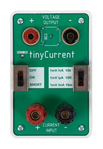
The TinyCurrent is a cute and cheap device to convert current into voltage which you then connect to your oscilloscope. This is a simple opamp across three switch selectable shunt resistors to select the range. The switch is the main limitation of this device as the dynamic range isn’t enough to cover the milliamp awake mode to the sub microamp sleep mode transition. Since it’s a simple analog conversion of current to voltage, it is easy to connect to a scope along with several GPIOs. Measuring the deep sleep current must be done with a DMM or other device but this works fine to quickly see when the device is in deep sleep or active modes.
Silicon Labs AEM
Silicon Labs Advanced Energy Monitor (AEM) is the primary power measurement tool for Z-Wave developers. A WSTK (BRD4002) developer’s kit is required to run the AEM which you can now purchase by itself instead of part of a more expensive kit. The AEM supplies 1.8-3.6v up to 500mA with a 100kHz sample rate and a resolution just under 1uA. There are four digital logic inputs as well as the VCOM UART. The Energy Profiler is a tool within Simplicity Studio that provides a graphical interface for the AEM. I found the energy profiler tool suffers from stability issues but is capable.
JouleScope
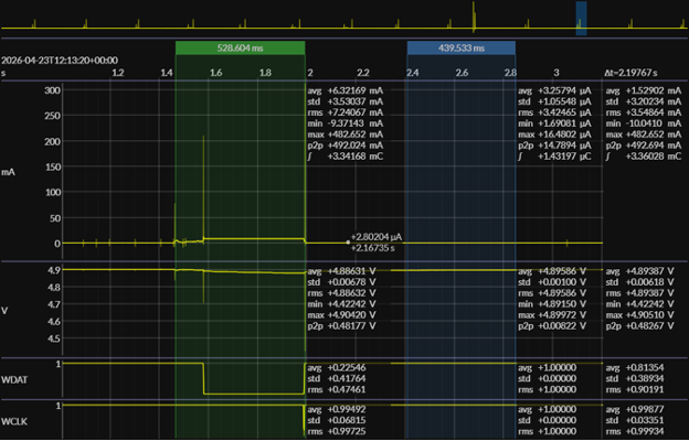
Joulescope is currently the industry standard for IoT development. While pricey, it is the perfect tool for the job. Full disclosure: Joulescope provided me with a JS220 for a previous project which I now use for every project. Wide voltage range of +/- 15V, 3A to 0.5nA resolution, 300kHz bandwidth and a reliable multiplatform software application make the Joulescope indispensable. The JS220 has 4 digital inputs and 2 outputs which help correlate current draw with the firmware being executed. The newer JS320 version is now available with even more dynamic range. The screenshot below shows the dynamic range from microamps to over 400 milliamps and two digital logic signals indicating the state of the CPU.
Oscilloscope Current Probe
Traditionally, an oscilloscope current probe was used for measuring current and simultaneously sampling several analog or digital channels. The problem with most of these probes is they were designed for high current (60A or more) and relatively low bandwidth and are very expensive, costing around a thousand dollars just for the probe without the scope. They do not have the dynamic range to go from nanoamps to milliamps and generally don’t have the resolution below milliamps. Maybe there’s one in a drawer somewhere you can use but I wouldn’t buy one of these for debugging IoT devices.
Next Steps
Part 8 of the Z-Wave Developer’s Journey discusses sub-GHz antennas which can make or break a Z-Wave product. The distance a Z-Wave product can be from the hub is determined by the efficiency of the antenna. I’ll discuss a few key factors in low-cost antenna design from my experience of having deployed many different types of antennas. As we continue along the Z-Wave Developer’s Journey, I welcome your comments and questions. Please feel free to reach out to me directly via email.
About the Author
Eric Ryherd has been at the forefront of Z-Wave innovation since 2003, beginning as a consultant and later serving as a Field Application Engineer at Silicon Labs. Over the course of his career, he has contributed to the design and development of a wide range of Z-Wave products, including sensors, remote controls, motorized window shades, and in-wall dimmers, many of which are on the market today.
Although he “retired” in 2022, Eric remains deeply engaged in embedded systems and Z-Wave development through his blog, DrZWave.blog, and ongoing IoT consulting projects. He is also a familiar face at Z-Wave Alliance Unplug Fests, where he frequently serves as the lead coordinator, supporting interoperability and developer collaboration.