
Antennas for Z-Wave
Explore the fundamentals of Z-Wave antenna design, from antenna types and impedance matching to RF tuning and best practices for optimizing wireless performance, range, and reliability in IoT devices.
Introduction
The antenna is the most important element of a wireless IoT product. A well designed and tuned antenna means the product “just works” in most customers’ home. A poorly designed antenna that has not been tuned will result in one-star reviews and quickly get on the “products to avoid list”. Fortunately, there are a lot of resources to help engineer an antenna that fits the needs of your product. This post goes over the many antenna options and some of the best practices to get the best RF performance.
Hub Antennas are Critical
Early in my Z-Wave consulting career I assisted a company who had recently added Z-Wave to their Smart Home controller using a
plug-in expansion board. The tiny board with a 500 series Z-Wave chip had a 20-pin header to the motherboard. The problem with this plug-in board was that the antenna was positioned in the center of the 8×6 inch motherboard. The antenna was also just a simple 7 mil trace around the edge of the PCB with the ground plane just a couple of millimeters away and had no impedance matching circuitry. This was about as bad an antenna as I have seen. Their customers complained the controller had only about 10 feet of RF range which I quickly confirmed. The CEO of the company stated that the RF range didn’t matter since Z-Wave is a mesh so it will find a route to all the other devices in the home. While the mesh will help, it does mean that at least one device with a decent antenna was required to be placed next to the controller. The poor range meant every command had to be repeated, resulting in latency and excess Z-Wave traffic that tended to clog the network when many commands were sent in sequence (for example at sunrise or sunset). My solution was to flip the PCB around and place the antenna against the edge of the plastic enclosure and increase the size of the ground plane of the plug-in board. Once I tuned the PCB antenna, the RF range met the Z-Wave certification requirement of 40 meters and customer complaints dropped dramatically. Unfortunately, the poor RF range gave Z-Wave a bad reputation in the vendors community. The problem was their poor antenna design and not the Z-Wave protocol itself. Key take away: Always design the very best antenna possible especially when designing a controller. See the Home Assistant ZWA-2 for the best antenna design I have seen so far.
Physics of Sub-GHz Antennas
Z-Wave devices often use monopole antennas where the ground plane provides the reference. Z-Wave chips have separate RF in and out pins. The separation of the RF in/out provides paths for filtering and impedance matching. The power output of the RF Out pin is quite high whereas the RF input needs high sensitivity and is thus switched out whenever the chip is transmitting. A set of passive components recommended by the chip vendor provides impedance matching to 50 ohms and some filtering. It is critical to implement these circuits as closely as possible to the silicon vendors’ recommendations. At one point, the two signals are at the desired 50-ohm impedance and are joined together and then connected to the antenna. The key metric of any antenna is its efficiency – how much of the electrical energy is converted into the electromagnetic waves transmitted into the air – usually denoted as the Q factor.
Just like a guitar string, an antenna has a resonant frequency. The antenna is most efficient at its resonant frequency, so it is important to tune it as close as possible. The length of the antenna is given by the equation the speed of light divided by the frequency: wavelength=3×10⁸/900MHz or 0.33m. Fortunately, for monopole antennas a ¼ wavelength is all that is needed which is 8.3 centimeters or 3.2 inches. This is just the theoretical starting point and adding an enclosure, batteries, the PCB material and nearby environment conspire to alter the theoretical length of the antenna. Techniques for making the antenna even shorter are required as most IoT products are much smaller than 3 inches on a side.
Antenna Types
I often quote that even a paperclip soldered to the pin of a Z-Wave module will meet certification requirements of 100 meters of RF range. While I haven’t actually tested this, I have worked on so many antennas that it does seem it will work. There are many types of antennas and below is just a partial list. Do you have a unique antenna? I’d like to see it! Send me an email with a photo and how far it can reach.
PCB
PCB antennas are the most common Z-Wave antenna due to their low cost and simple design. All you need is a little extra PCB space and to follow a few simple design rules. PCB antennas include simple L, meander, inverted F, fractal and more than I can possibly list here.
The early Zensys developers kit recommended a simple L shaped antenna shown here from the datasheet. This antenna works well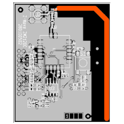 and easily achieves the required performance for Z-Wave certification. The one challenge with all PCB antennas is that the radiation \pattern is not uniform and often has nulls and gain in certain orientations. Remember that the regulatory requirements will identify the orientation with the strongest signal. If that orientation has antenna gain, you may have to reduce the transmit power to stay under the regulatory requirements. Lowering the transmit power will reduce the RF range in all other directions. Z-Wave certification will check the RF range in all 6 orientations. You may need to redesign your PCB antenna to make the radiation pattern more uniform. Antenna redesign can be a time consuming and expensive process.
The Inverted F antenna is popular with 2.4GHz antennas as it has good performance and is small. But in the 900MHz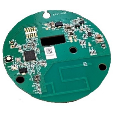 band the antenna is large as shown here. If you have PCB real estate, it can be a good option. The thing I have a hard time wrapping my head around is that the antenna is connected directly to ground. Seems like that would short it out, but instead it anchors the resonant standing wave so it works but needs to be carefully tuned.
Meander antennas are commonly used in space constrained applications. A meander antenna simply folds the wire back and forth a number of times to compress the PCB space required. The Silicon Labs BRD4205 has an example meander PCB antenna which is selectable by installing a 47pF capacitor and removing the one for the SMA connector. The PCB shown here is from a remote control that has a unique spiral antenna that has great RF performance.
Wire
Wire antennas fall into two broad categories: flexible and stiff. Flexible antennas are like the one shown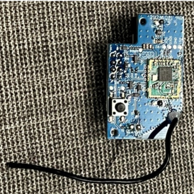 here which, as the name implies, is a simple stranded wire cut to a specific length. The wire is ideally held in a known orientation using plastic standoffs but there are many products that are stuffed into a wall box with the antenna stuffed alongside all the other wires. The problem with flexible wires is that it is impossible to account for the impedance shift due to adjacent materials. The length is also hard to consistently manage in manufacturing as even a one-millimeter variation can change the antenna performance. A simple wire is low-cost and works reasonably well especially for space constrained applications.
The second category is a stiff wire or stamped metal. The wire is typically pre-cut and bent at the 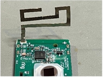 factory with precision and then hand soldered in place. This results in a repeatable and predictable environment meaning it is possible to accurately tune the antenna for optimal performance. The other advantage is that the antenna is usually held vertically off the PCB ground plane yielding a better radiation pattern than a PCB antenna. The antenna can be stamped metal in any shape allowing for more flexibility in optimizing performance as shown here.
Helical
Helical antennas can be quite small but can have decent performance if properly tuned. The Z-Wave UZB USB stick controller uses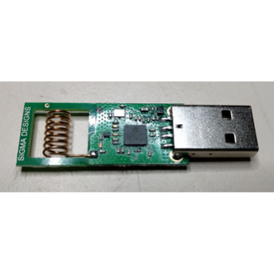 a small helical antenna as shown here. The challenge with making the antenna so small is to understand that the ground plane is also part of the antenna. Thus, a tiny ground plane reduces performance. The other problem with USB sticks is that they are often plugged directly into a PC or a Raspberry Pi. A computer has many components and oscillators that generate a significant amount of RF noise. In addition, the orientation may be less than optimal. The recommendation is to put the USB stick on a USB cable of at least one foot in length. The cable isolates the USB stick from the noise from the computer and allows more optimal orientation.
I made a prototype PCB with a sort of helical antenna that used the 2 layers of the PCB and a lot of vias. However, it was difficult to tune and did not have good performance. I believe the problem was the plated thru-hole vias were significant impedance mismatches. Thus, I do not recommend trying to make a PCB helical antenna.
Chip
I personally have not had good experience with chip antennas, but I am aware of companies that have used them successfully. Chip 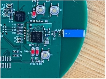 antennas are often the smallest antenna thus they are often used in very space constrained products. The challenge is that they are impacted by the nearby environment. The antenna must be carefully tuned with the enclosure, battery and mounting surface included in the tuning.
External
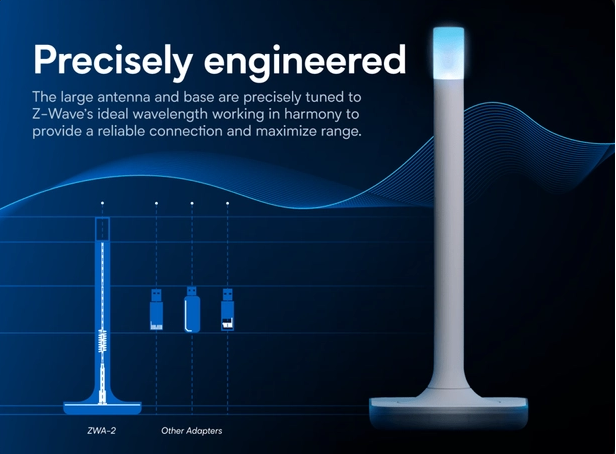
External antennas, often called whip antennas, are usually connected via an SMA or U.FL connector on the outside of the enclosure. External antennas can yield the best performance because the antenna is omnidirectional and has a donut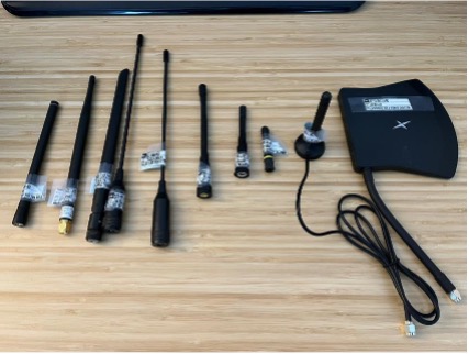 shaped radiation pattern resulting in some gain. They are typically the most expensive option and are normally only used by the controller or by a device that needs long range. Don’t be fooled into believing the claim that the antenna is 50-ohms and “tuned” for your chosen frequency. You must still tune it. I tested all the antennas shown here and they vary widely in performance. The more expensive antennas were not the best. In fact, one of the cheaper antennas nearly matched the performance of the most expensive. However, one of the popular antennas turned out to be terrible. The Home Assistant ZWA-2 uses a giant screw-in antenna and has by the far the best RF range of any device I’ve tested.
Module or SoC
The module versions of Z-Wave chips generally include the impedance matching circuit in the module itself. Only a simple PI network is needed to tune the antenna. The SoC version requires more matching circuitry but has the benefit of more transmit power and more flexible filtering.
Impedance Matching Circuit
The output of the Z-Wave SoC chip is high-impedance but for optimal antenna performance, the impedance needs to be transformed 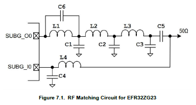 to 50-ohms. Each silicon vendor has their own recommended circuit to match the chip to the 50-ohm antenna. Silicon Labs 800 series integration guide (UG517) has the circuit shown here. After this circuit, another Pi network is used for filtering and tuning the antenna. The filtering is necessary to ensure regulatory requirements (FCC in the US) are met.
Tuning the Antenna
Tuning the antenna starts by taking a bare PCB, attaching a coax cable or SMA connector to the entry into the Pi network with a 47pF 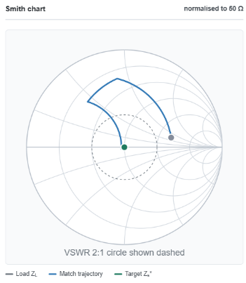 series capacitor. Calibrate a Vector Network Analyzer (VNA) to remove the parasitics of the cable/SMA. Then connect the PCB to get the Smith chart of the antenna. Next, use the tool from everythingrf.com to design a Pi circuit that will tune the antenna to 50 ohms. The recommended circuit is an IDEAL circuit using ideal devices. However, we live in the real world and must use real devices which have parasitics that will skew the result. Choose RF components as close as the recommended values as possible and install them one at a time. I try to avoid component values under 3pF or 3uH as other parasitics can detune the antenna with these small values. Measure the impedance at each step which should move along the path shown but won’t be exact. Try different values until the VSWR is below 2.0, ideally under 1.0. If you have a wire or PCB antenna you can shift the frequency by shortening the antenna but you can’t make it longer. I usually make a PCB antenna 10% longer than the calculated value to allow for trimming during tuning. Cut just 1mm at a time as it can make quite a difference. Tuning is typically a half-day effort of trial and error and sometimes involves a complete redesign of the antenna itself.
Can One Antenna Work for All Regions?
Yes. One antenna can work for all regions – from 868MHz to 920MHz. But you need an antenna with sufficient bandwidth to do it. For optimal performance, slightly different Pi network component values are required for each end of the spectrum. The recommendation is to optimally tune the antenna for the primary target market with perhaps a shift towards a secondary market. For example, if the primary market is the US (908-920MHz) and the EU is secondary (868MHz), tune the antenna for 908MHz or slightly lower. Even if the antenna isn’t optimally tuned, it will still work if the bandwidth is wide enough.
Antenna Best Practices
- No metal within 6mm of the antenna
- Ground plane, batteries, enclosure
- Impedance matched and tuned for target market with enclosure
- Including typical installation surface within 6 inches
- VSWR below 2 at target frequency
- Initial PCB antennas are 10% longer than calculated to ease tuning
- Continuous ground plane(s) with array of vias
- RF signals on a single layer and surrounded with ground vias
- Measure the radiation pattern in all orientations
- Prevent strong gain in one orientation resulting in failing regulatory testing
Next Steps
Part 9 of the Z-Wave Developer’s Journey discusses the regulatory process for subGHz devices in the US. I will present the tests you should perform before going to a test house and the tools you’ll need. As we continue along the Z-Wave Developer’s Journey, I welcome your comments and questions. Please feel free to reach out to me directly via email.
About the Author
Eric Ryherd has been at the forefront of Z-Wave innovation since 2003, beginning as a consultant and later serving as a Field Application Engineer at Silicon Labs. Over the course of his career, he has contributed to the design and development of a wide range of Z-Wave products, including sensors, remote controls, motorized window shades, and in-wall dimmers, many of which are on the market today.
Although he “retired” in 2022, Eric remains deeply engaged in embedded systems and Z-Wave development through his blog, DrZWave.blog, and ongoing IoT consulting projects. He is also a familiar face at Z-Wave Alliance Unplug Fests, where he frequently serves as the lead coordinator, supporting interoperability and developer collaboration.